Final Project

Final Project WOOOOOOO
In starting to plan for the final project, the project that I am leaning towards is heated clothing, specifically a thin, wearable vest that has heating elements on it. This would be built such that I could wear it underneath any of my existing jackets, and it would be easily washable if need be. With that in mind, here is the bill of materials that I came up with:- Arguably the most crucial aspect of the heated vest is the heating element. I think that the best and cheapest way to make this happen would be to use positive temperature coefficient (PTC) heating pads. They are quick to warm up and they are able to self regulate their own temperatures to avoid overheating and causing a fire under my jacket. I also want them to cover a decent amount of area. I was thinking about using 4 or 6 (see battery discussion) of these heating pads
- I also will need a battery to power these heating elements, which seems like it will be the most challenging and expensive item. I would like to get at least 4-5 hours of battery life from this vest, and ideally I would like something closer to 6-8 hours of battery life for the full days that I will spend working outside in the cold. The easiest voltage to work with is 5V, as that is what both the microcontroller and the heating pads run on, but other voltages are viable with step-up/step-down converters. If I have 4 pads, each of which are drawing 600mA, I need the battery to be rated to at least 2.4A, but I would prefer if I had some more headroom, so I looked for 5V 3A batteries. Based on my (potentially incorrect) math, just powering the 4 heating pads wired in parallel and assuming no loss due to the rest of the electronics, a 10,000mAh battery gives me ~4 hours of battery life. Realistically, this would be less, so I want a higher capacity battery. A 20,000mAh battery would likely give me 6-7 hours of real battery life, so that is what I was looking at. I saw some batteries like this one that fit these requirements, but seem a little sketchy. However, I could pull some clever wiring shenanigans and get 6 heating pads, which would provide more warmth, and potentially use a less sketchy battery. If I wired 3 pairs of heating pads in parallel, with each pair wired in series, I would draw 10V and 1.8A of current, which is a (somewhat) compatible demand for lots of power banks that exist already for phones and laptops. I found this one, which is capable of outputting either 9V or 12V with USB PD and can handle 1.8A. It is a little big, but I think that this is the best way of handling power for this project, and it will be able to use 6 heating pads to keep me even warmer. It also is nice because with multiple ports, I can plug the microcontroller into a 5V port directly while also having 9V going to the pads.
- USB PD Trigger/Decoder board to get 9V out of the power bank (pads will run at 4.5V instead of 5V, but with more pads this should be fine) like this one
- JST connectors for modular pad connections for easy washing
- ESP32 or Xiao for the brains of the operation
- Power switch (rocker switch) and indicator LED
- Rotary encoder for temperature control
- Small screen to display battery level and temperature
- Temperature sensor (NTC thermistor maybe?)
- 22-24 AWG wire
- USB A to microUSB cable
- Polyester or neoprene to make the vest itself
- Waterproof material to make a pouch to house the microcontroller
- Velcro or snaps to make things easily removable for washing
- 3/27 - MVP: get ESP32 to turn the heating elements on and off
- 4/15 - Ramping it up: integrate temperature control into ESP32
- 4/29 - Learning to sew: make the vest itself
- 5/6 - Putting it all together: putting all the electronics onto the vest and buttoning it all up
Integrated Project
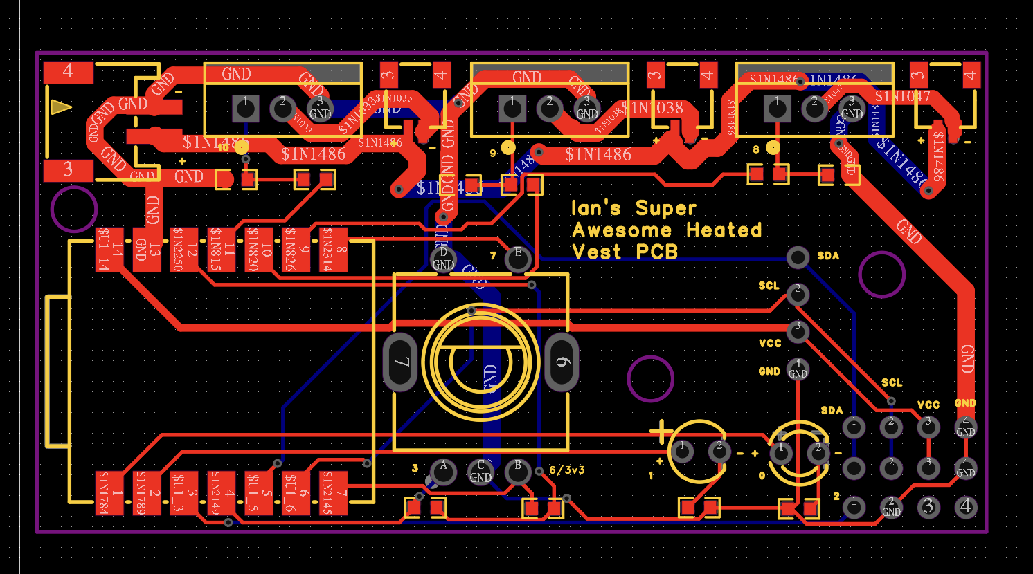
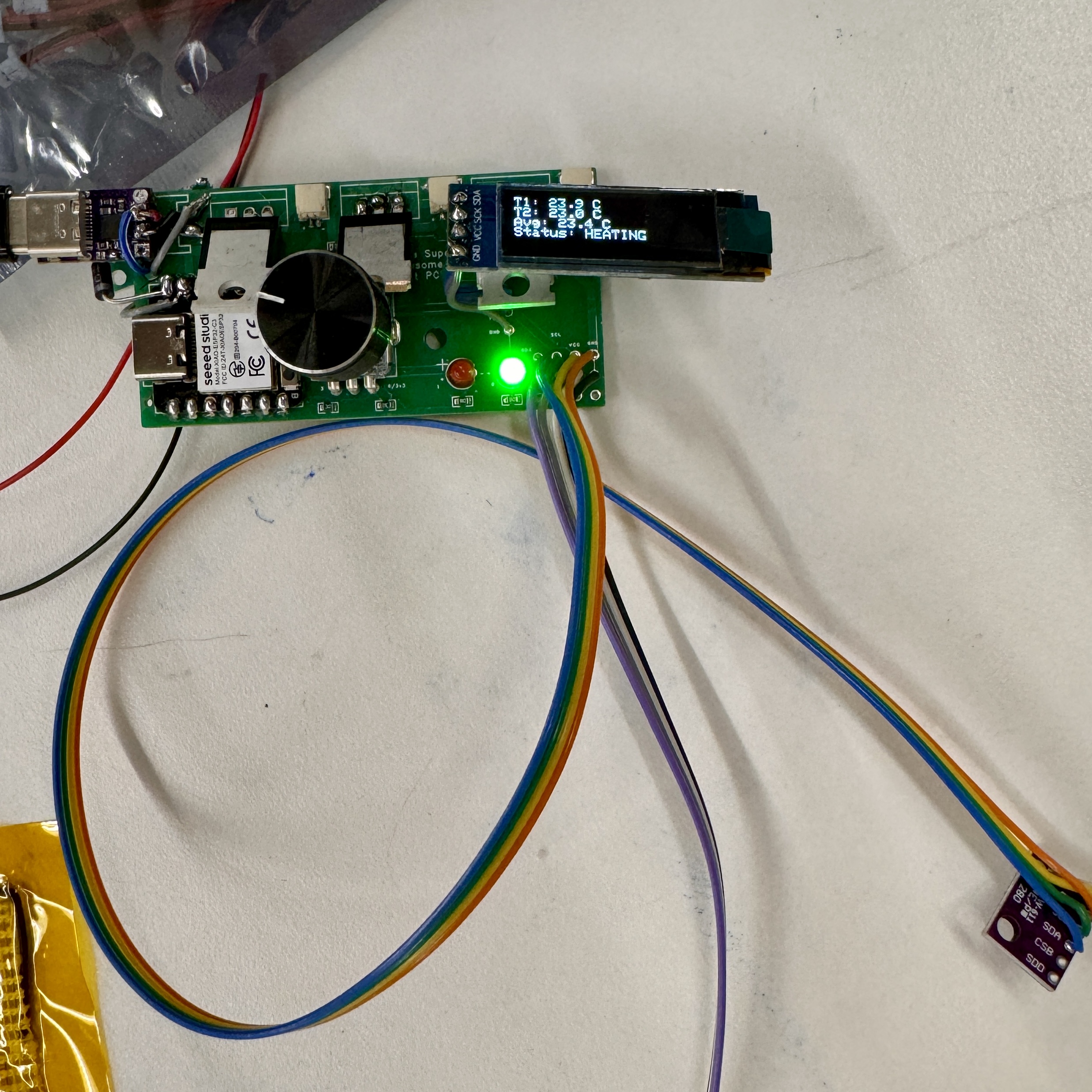
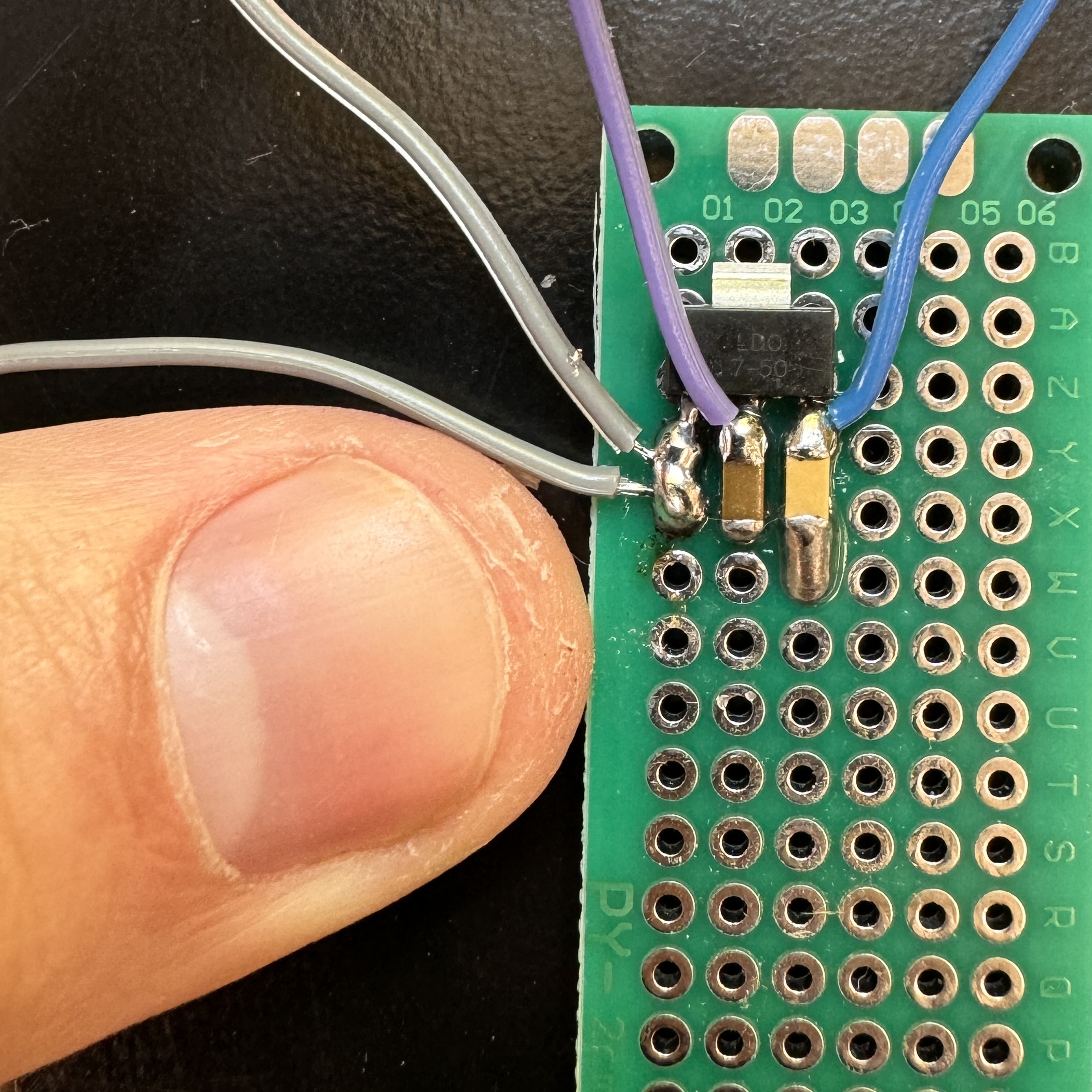
My working on the integrated project consisted of two parts - designing a PCB and learning to sew. The first part, designing a PCB was a slow-going process, but EasyEDA made the process relatively straightforward. The biggest challenge in this part was designing electronics without ever being able to actually test them - just hoping that they work. I did some preliminary breadboard testing to make sure that all of my theories were correct, but in the end it was essentially just scaling up my MVP to have three heat pads and work on two different power circuits. I have designed one other PCB before, but that one came with a mostly made gerber file already and just required some tweaks, so starting totally from scratch was tough. It took many hours of staring at datasheets from random websites and using the worst search function known to mankind on the LCSC website to find the parts that I was looking for, but once I did, I was able to plop them into the schematic. I connected the heat pads to a circuit that will use 12V input power, though I later realized that I could've streamlined this process since the PD trigger boards are female connectors and not male ones, so it would be board-side and not battery-side, so there is a space for a JST input connector on the board, but I will have to mount the trigger board separately. The LED and rotary encoder work on 5V power, and I added a small OLED screen mount so that I can easily display statistics like temperature and goal temperature. The rotary encoder will be harvested from a board that we already have in the lab, and the transistors are parts that we already have, so I only had the resistors surface mounted.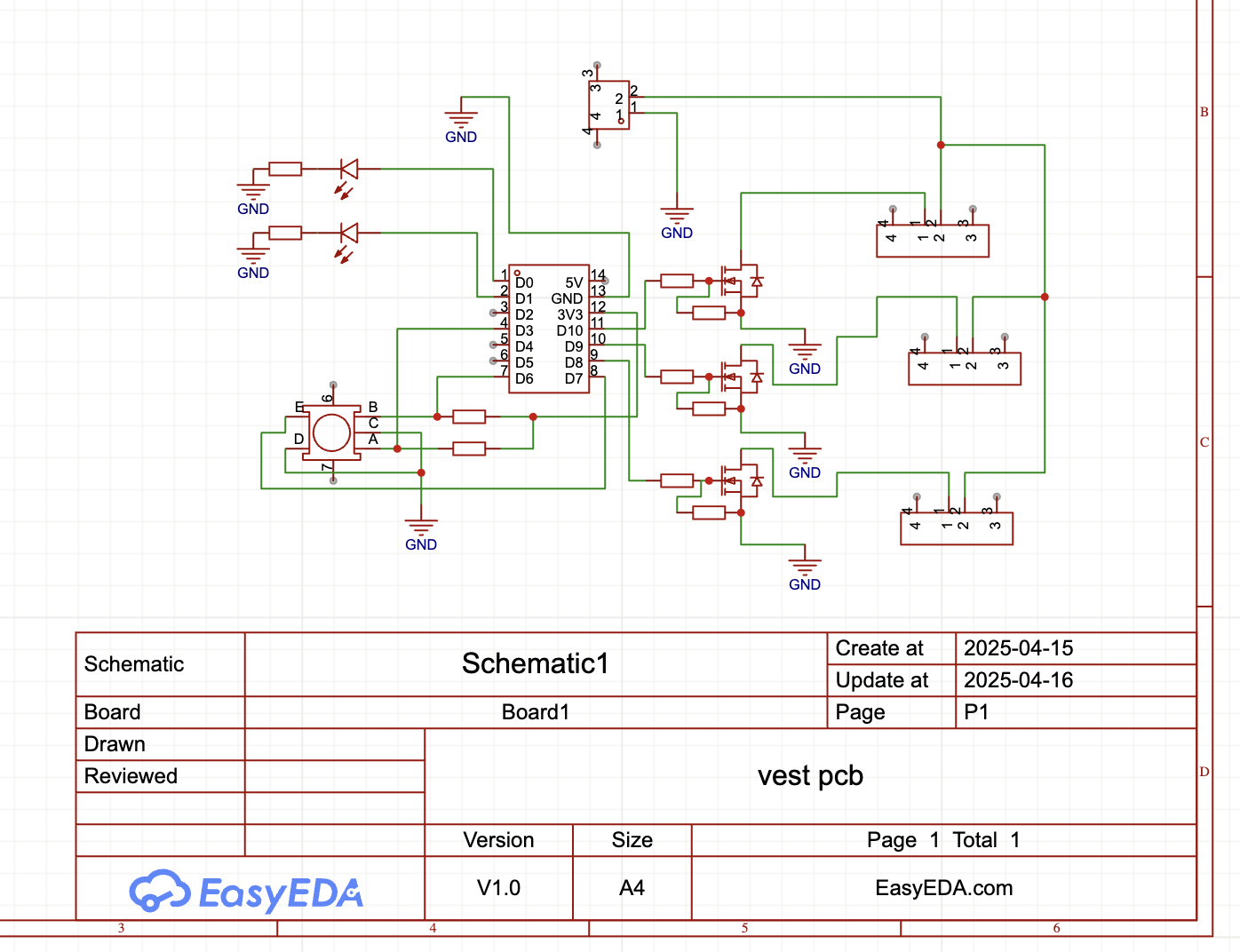
The Final Final Push
I genuinely think that I spent around 70-80 hours on this between Thursday of last week and Monday, so I am just going to go through the highlights here and not every single trial and tribulation. This was extremely fun and extremely frustrating all wrapped into one Diet Coke-fueled bender, but in the end I am proud of what I made, so I count that as a huge win. I will be breaking it down into smaller chunks of the project below for organizational purposes.The Vest
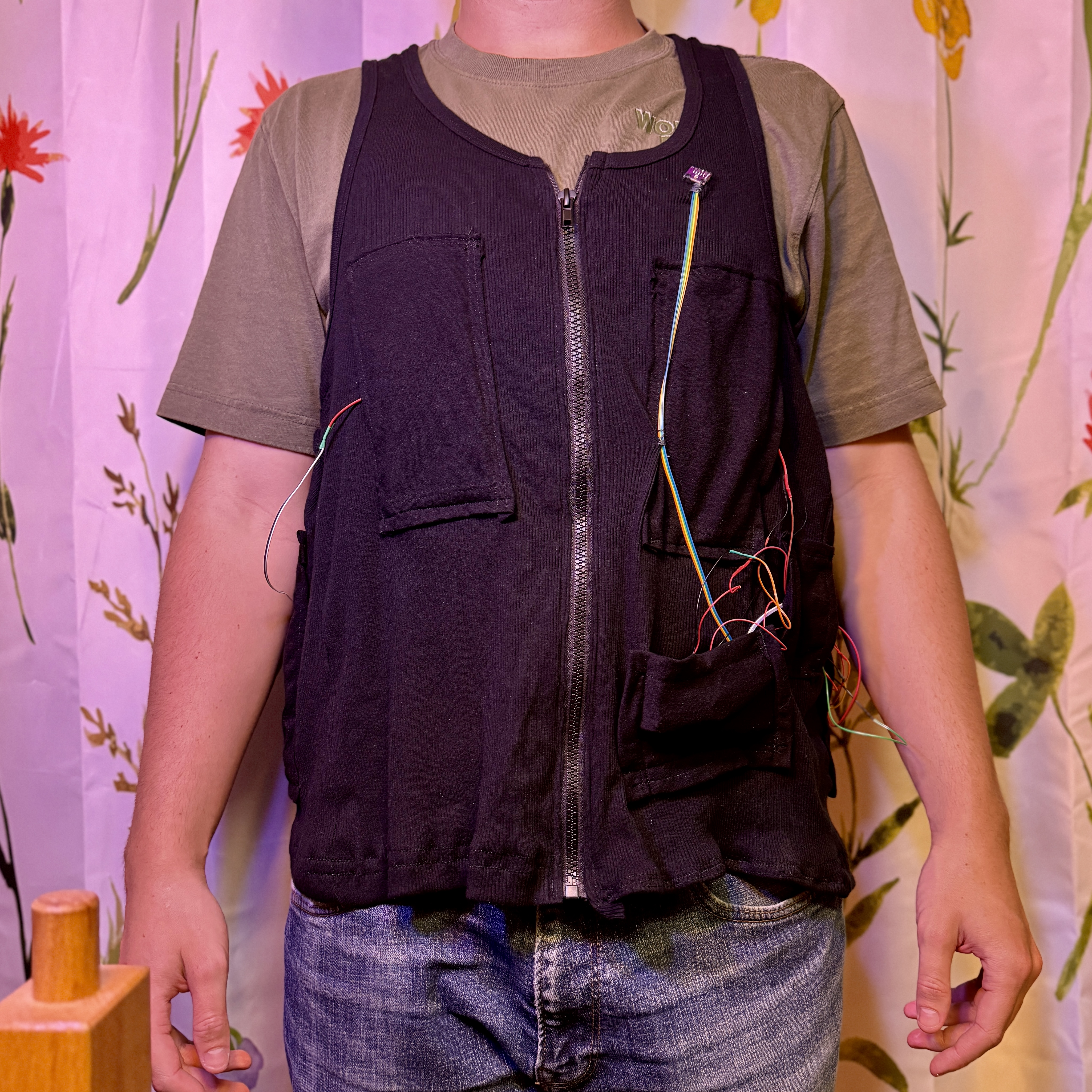
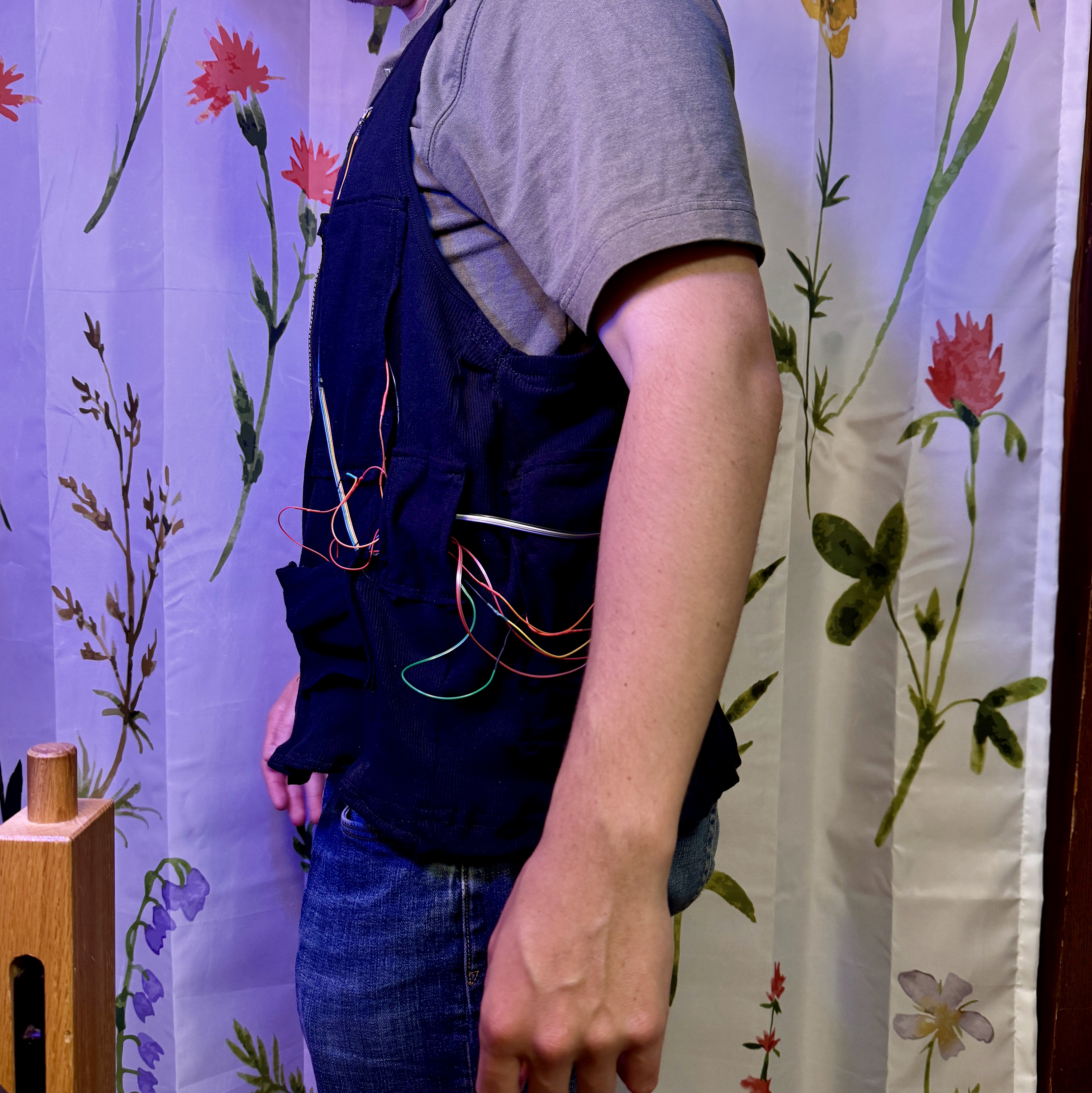
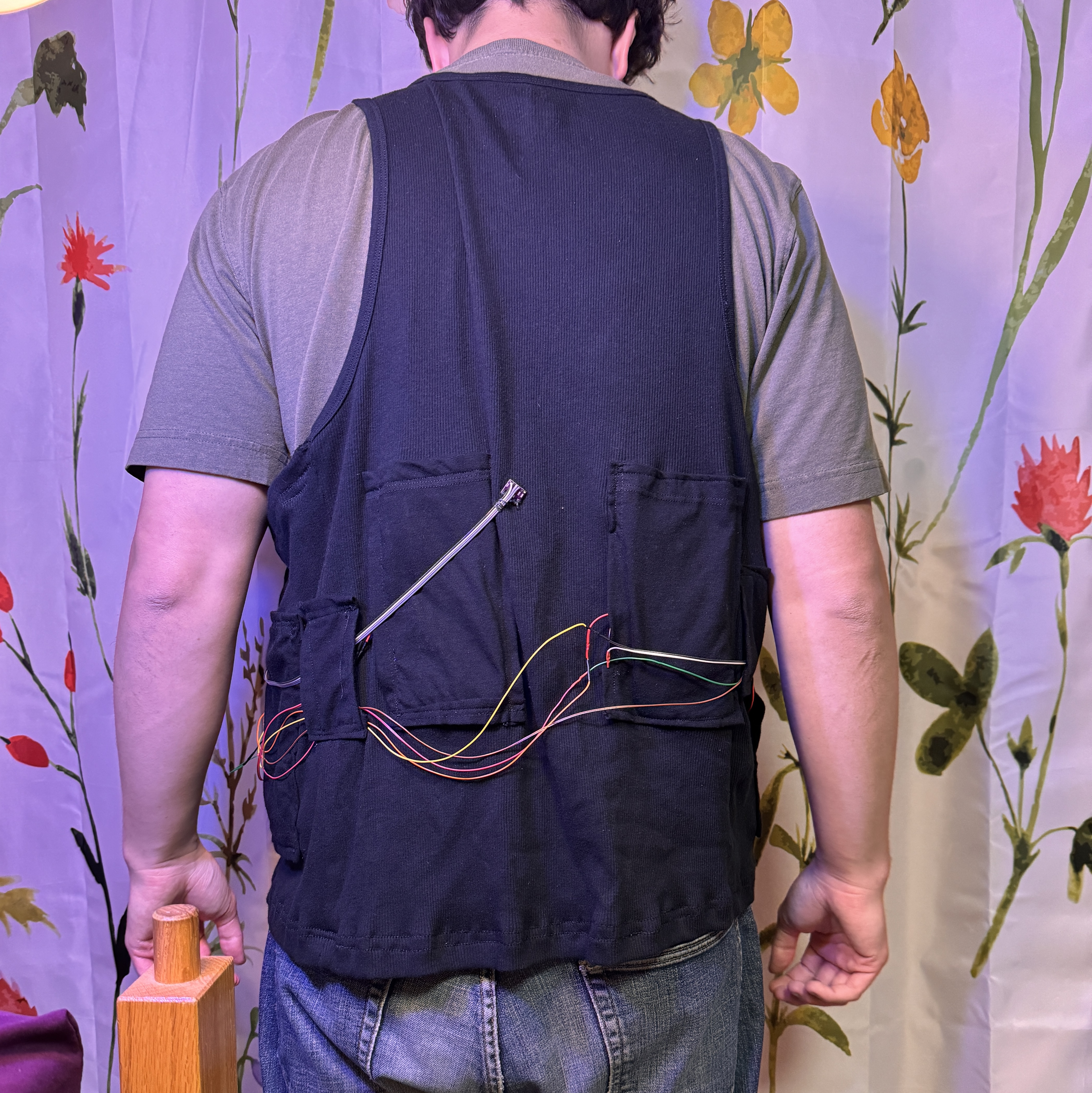
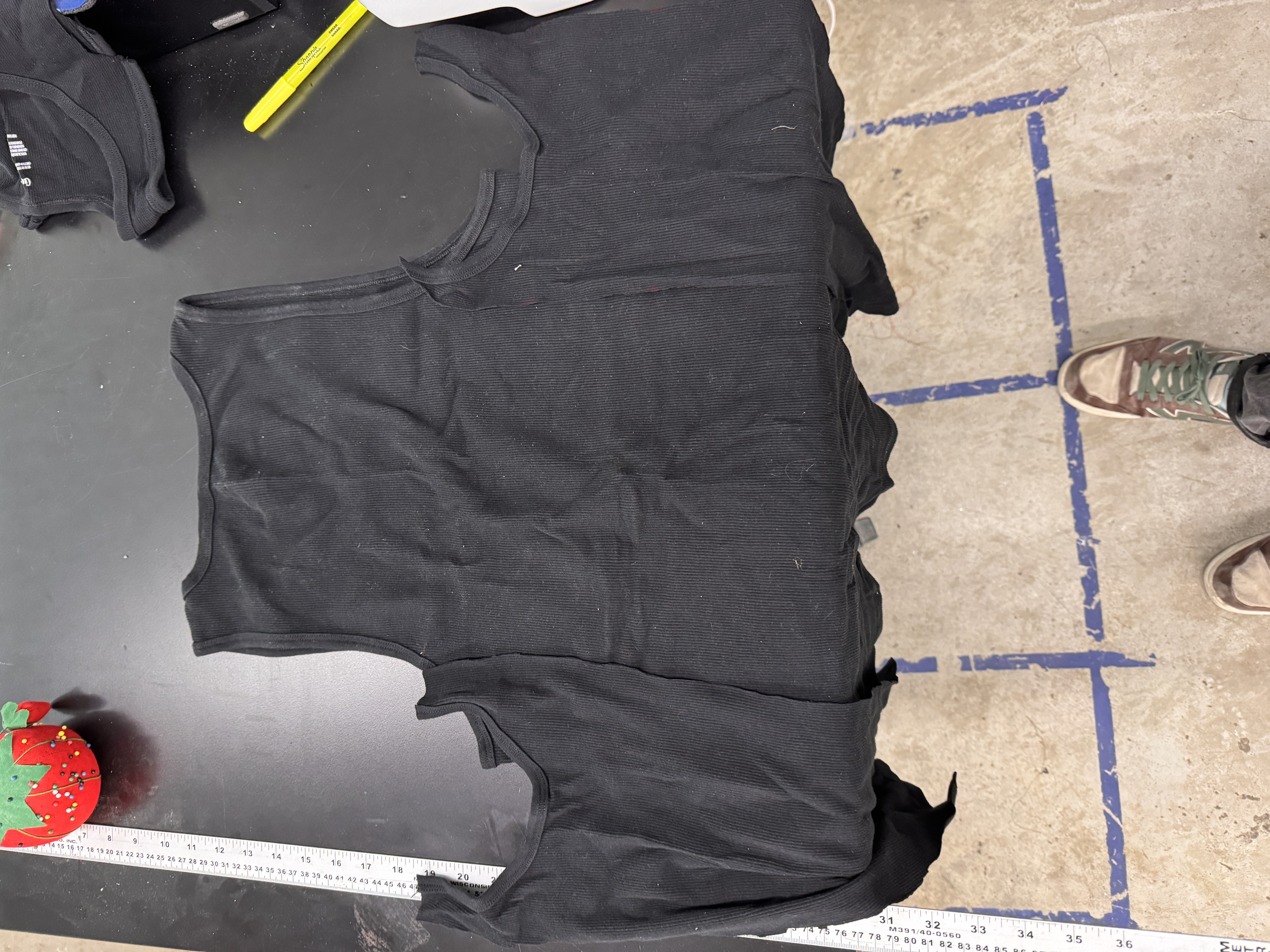
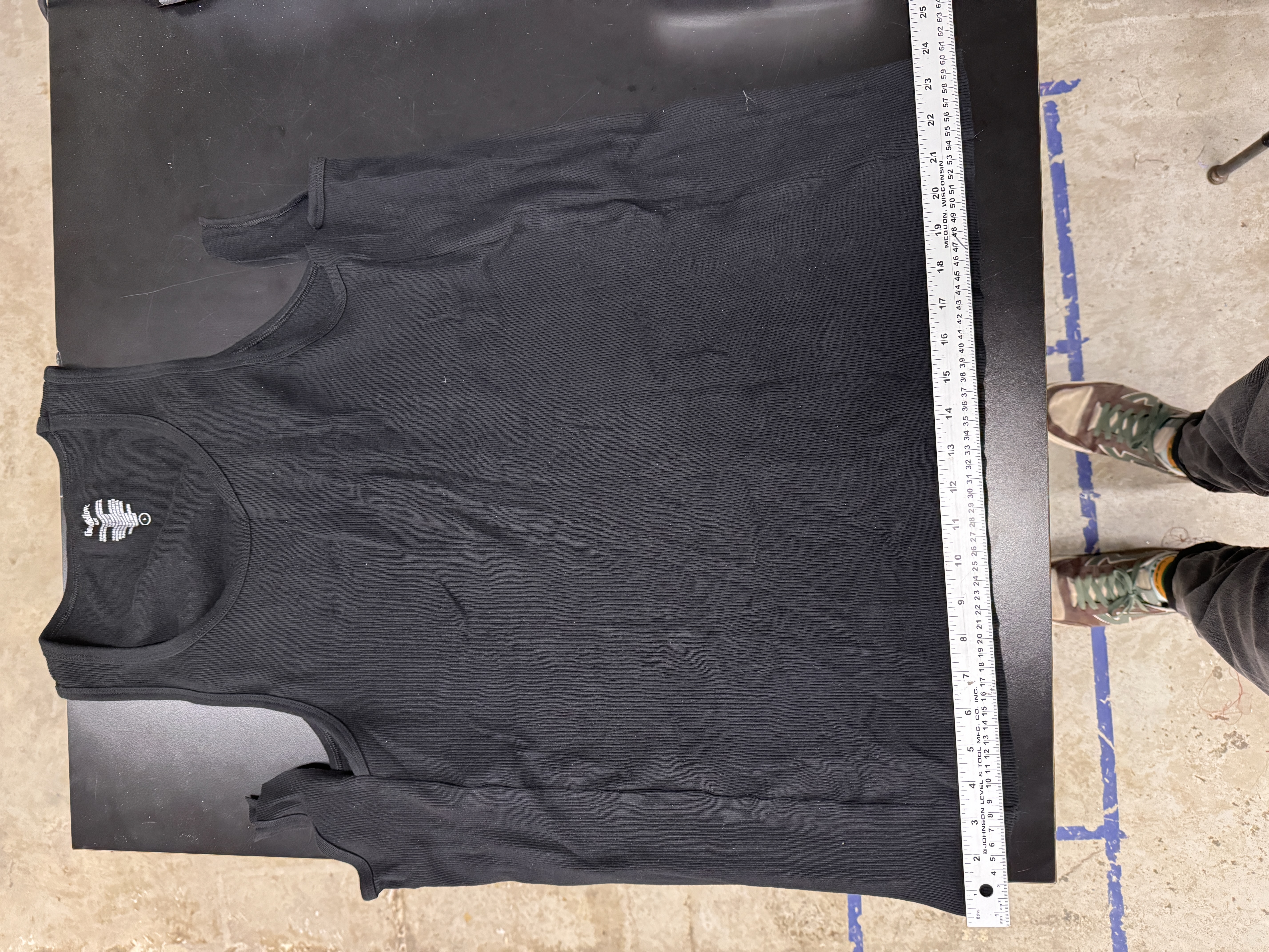
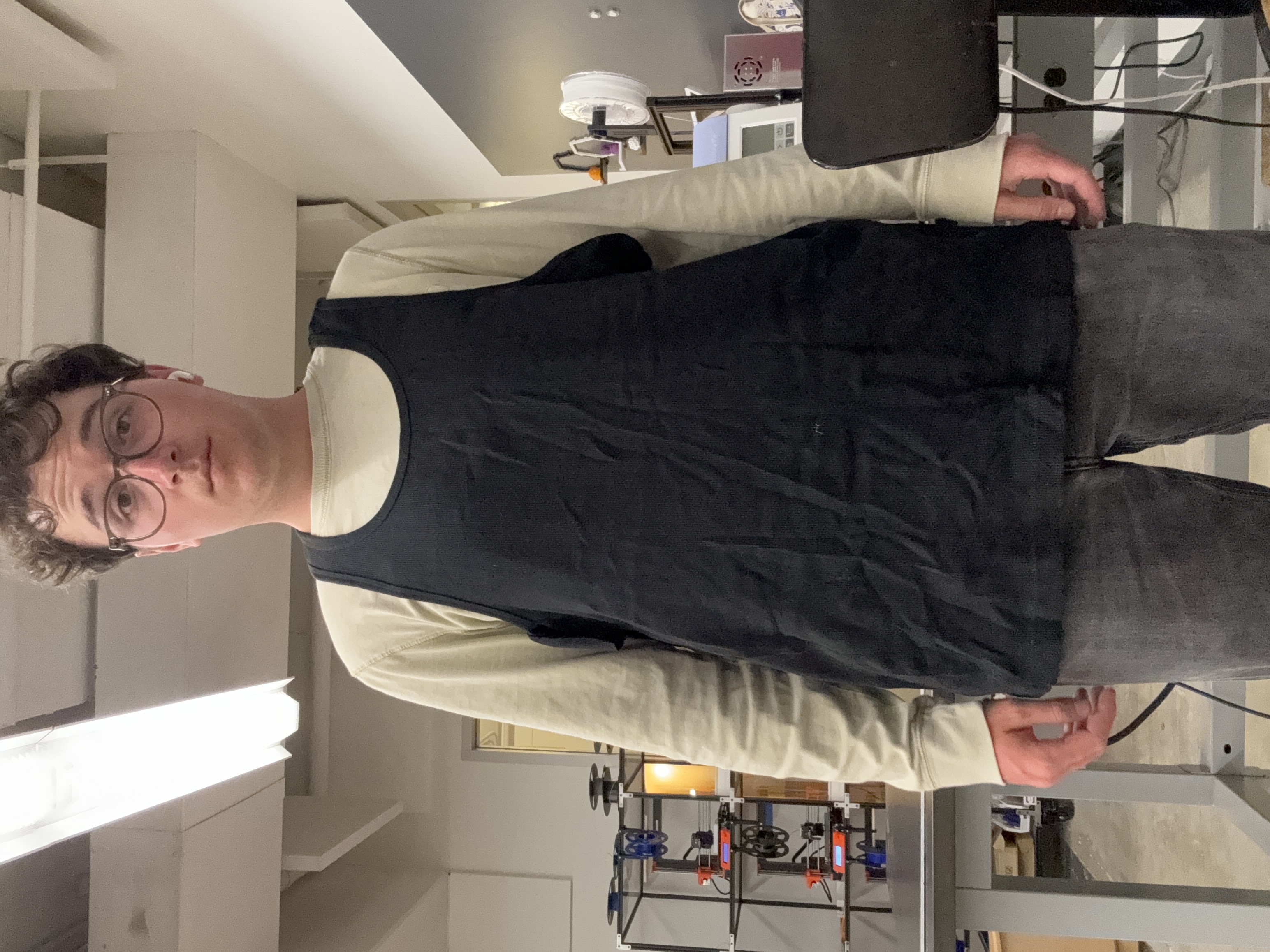
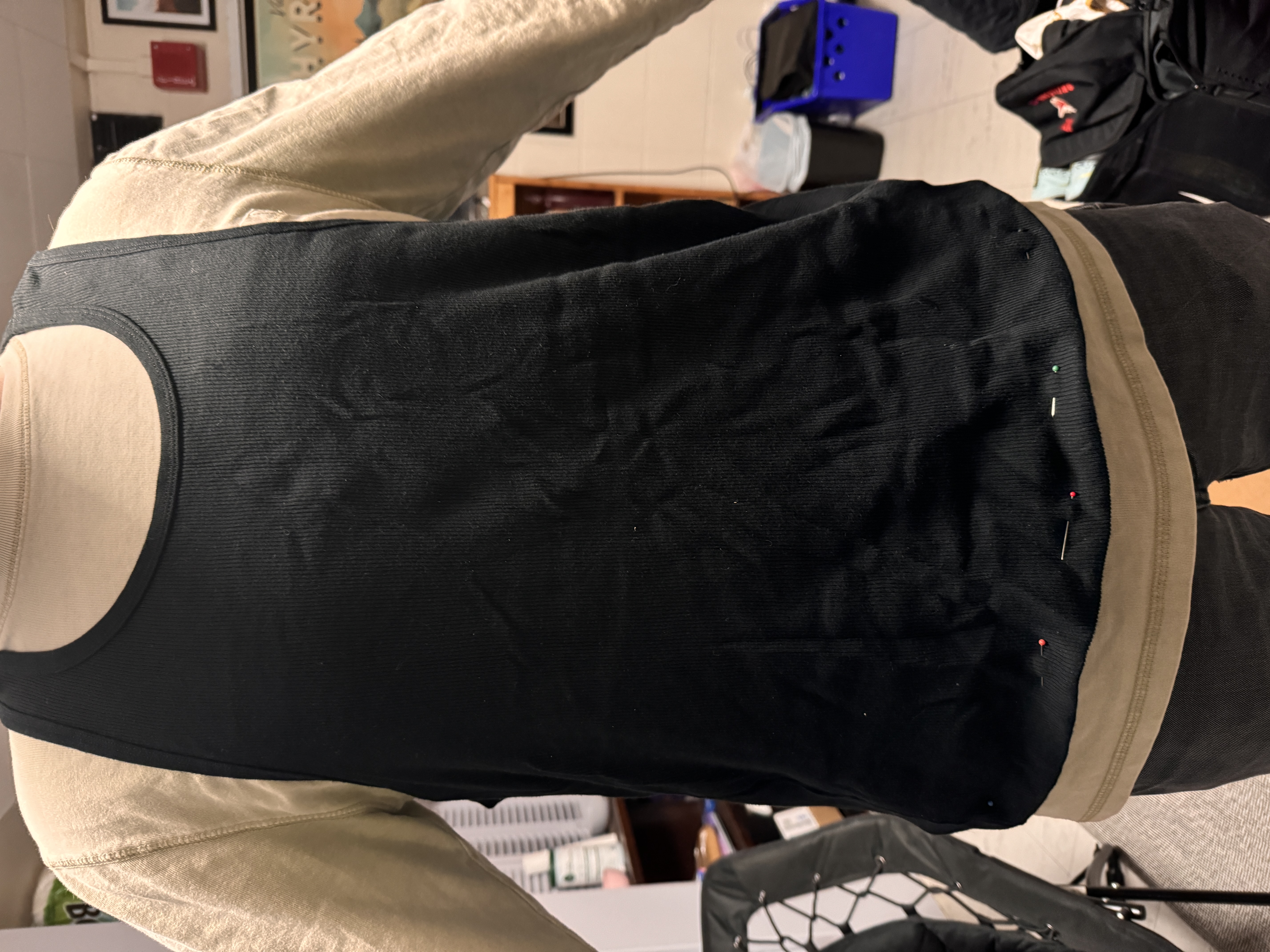
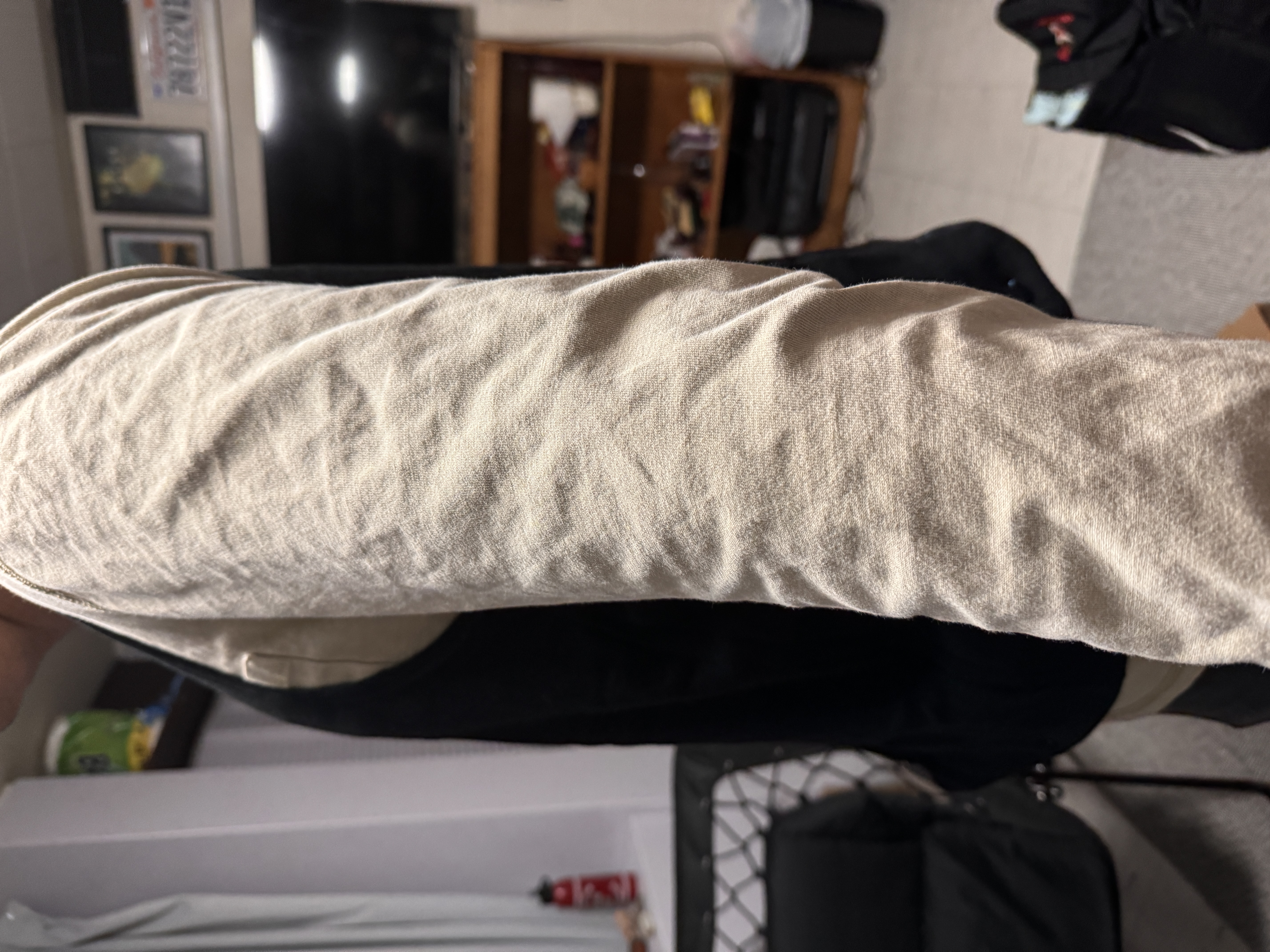
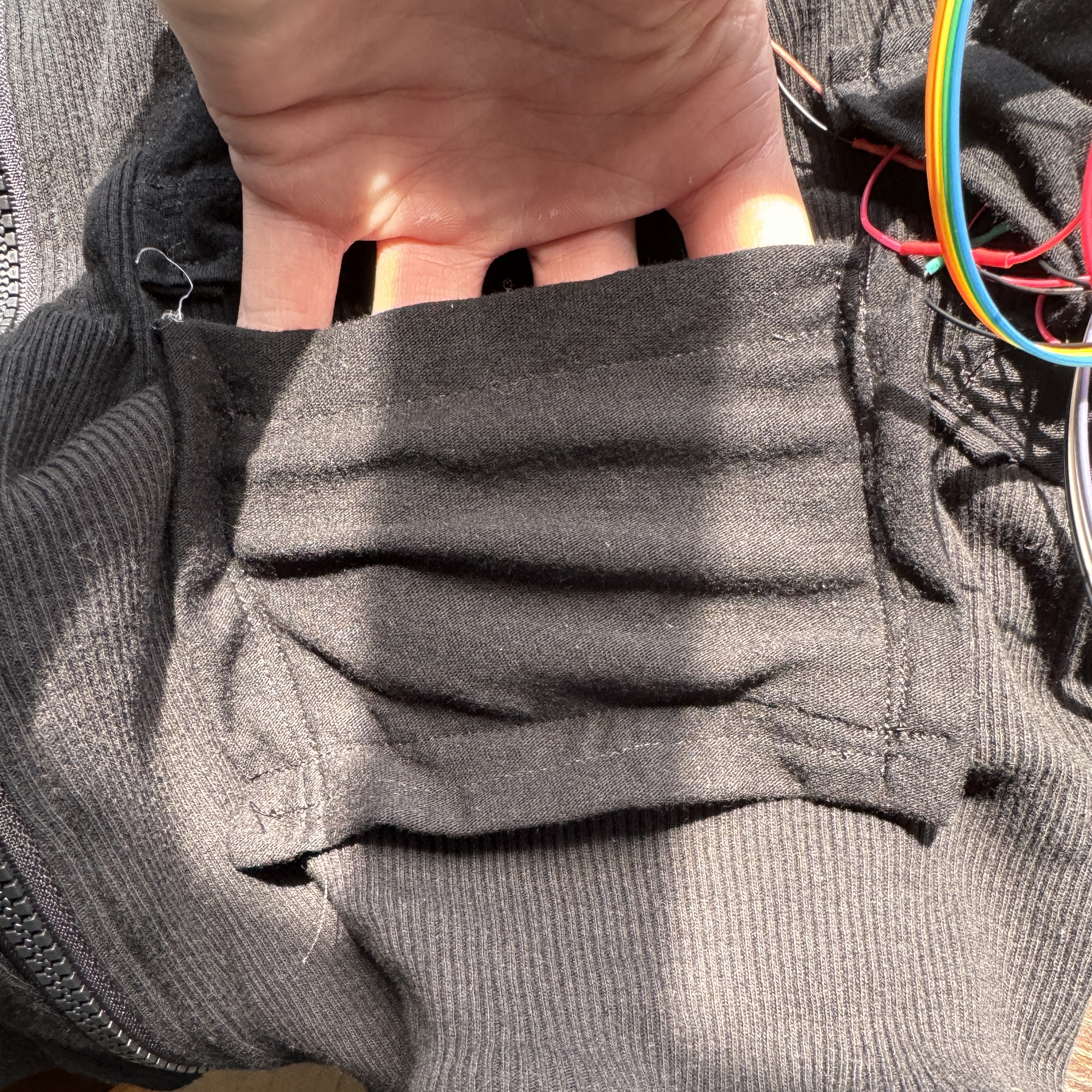
I think that if I was doing this project all over again, the first thing that I would change would be to use a different, less stretchy, and thicker material. The undershirts were very convenient for what I had on hand, but it was really frustrating and unforgiving to sew as it bunched, scrunched, and tore where other materials wouldn't have. At the end of my integrated project, I had made the barest of bones vest - it was the correct width and that was about it. The first thing that I did was get to hemming it and making it look less ridiculous. This again was the product of YouTube and Kassia Academy, and while it's not perfect, I was able to tailor it to my size pretty well. The length is perfect almost everywhere, except for one spot on my back where I accidentally hemmed it a bit too short, but it's only aesthetic and this is meant to be worn underneath things anyways. I also fixed the armpits in perhaps not the most elegant way, but I just folded the material over itself and stitched it, which brought the elephant ears in a bit.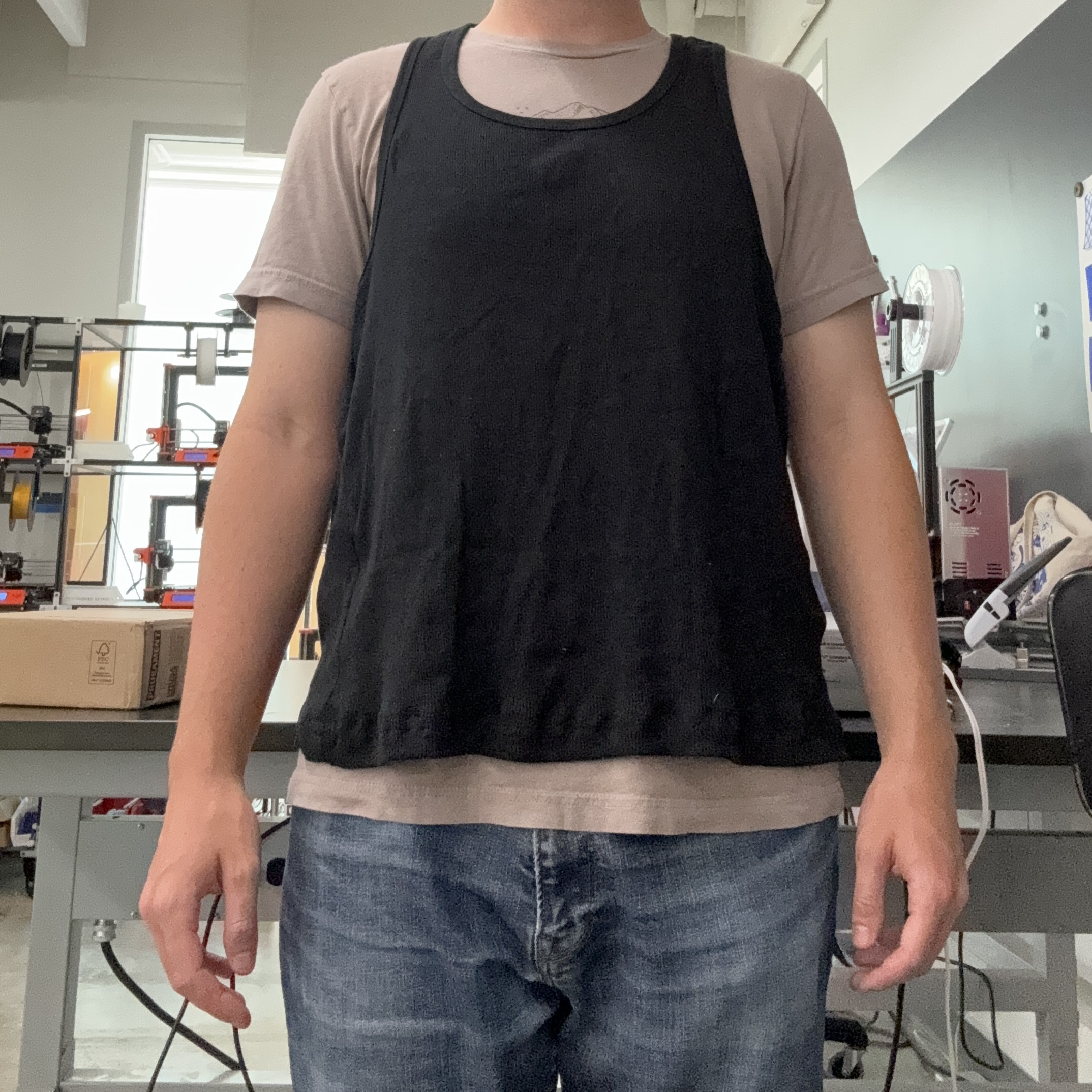
Heat Pads
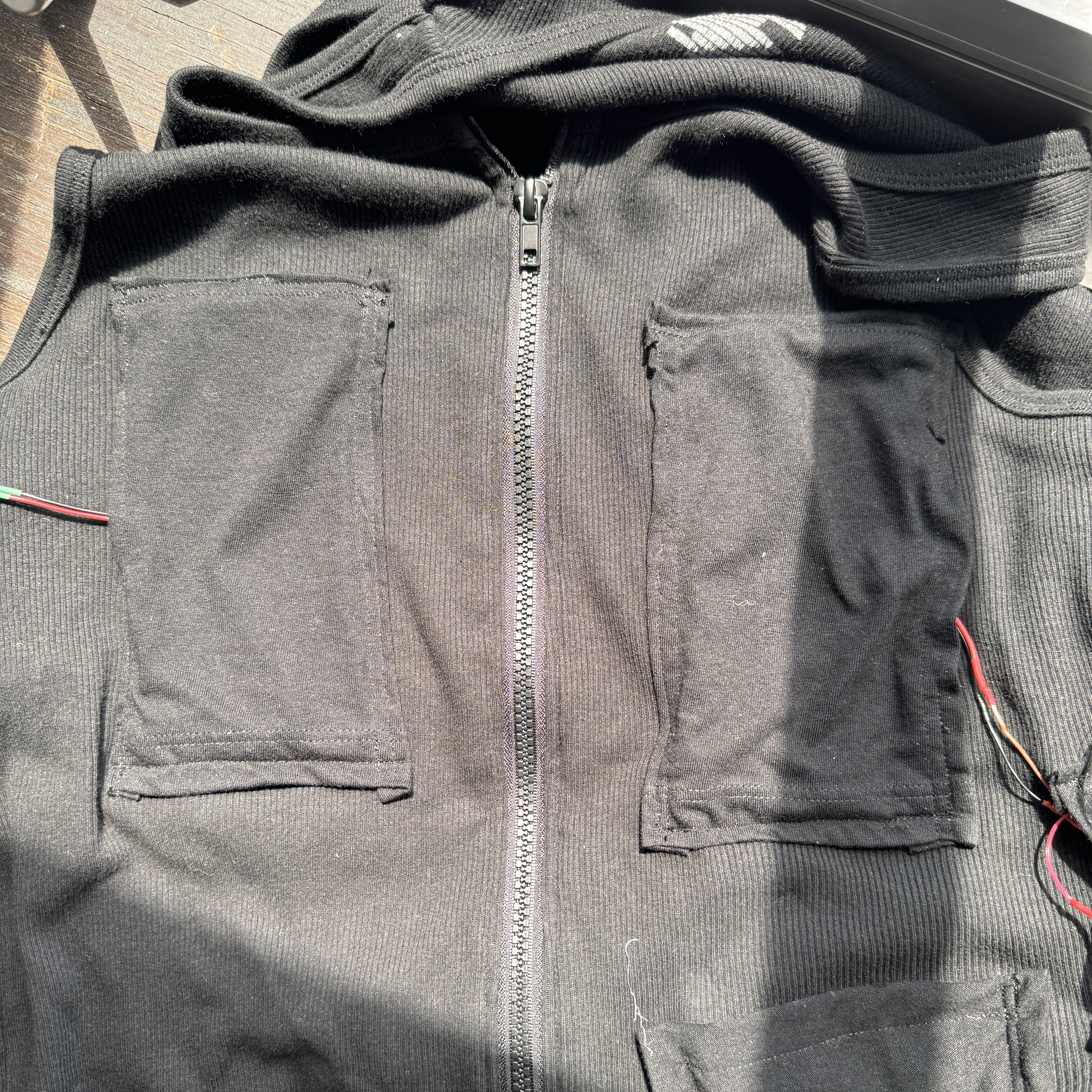
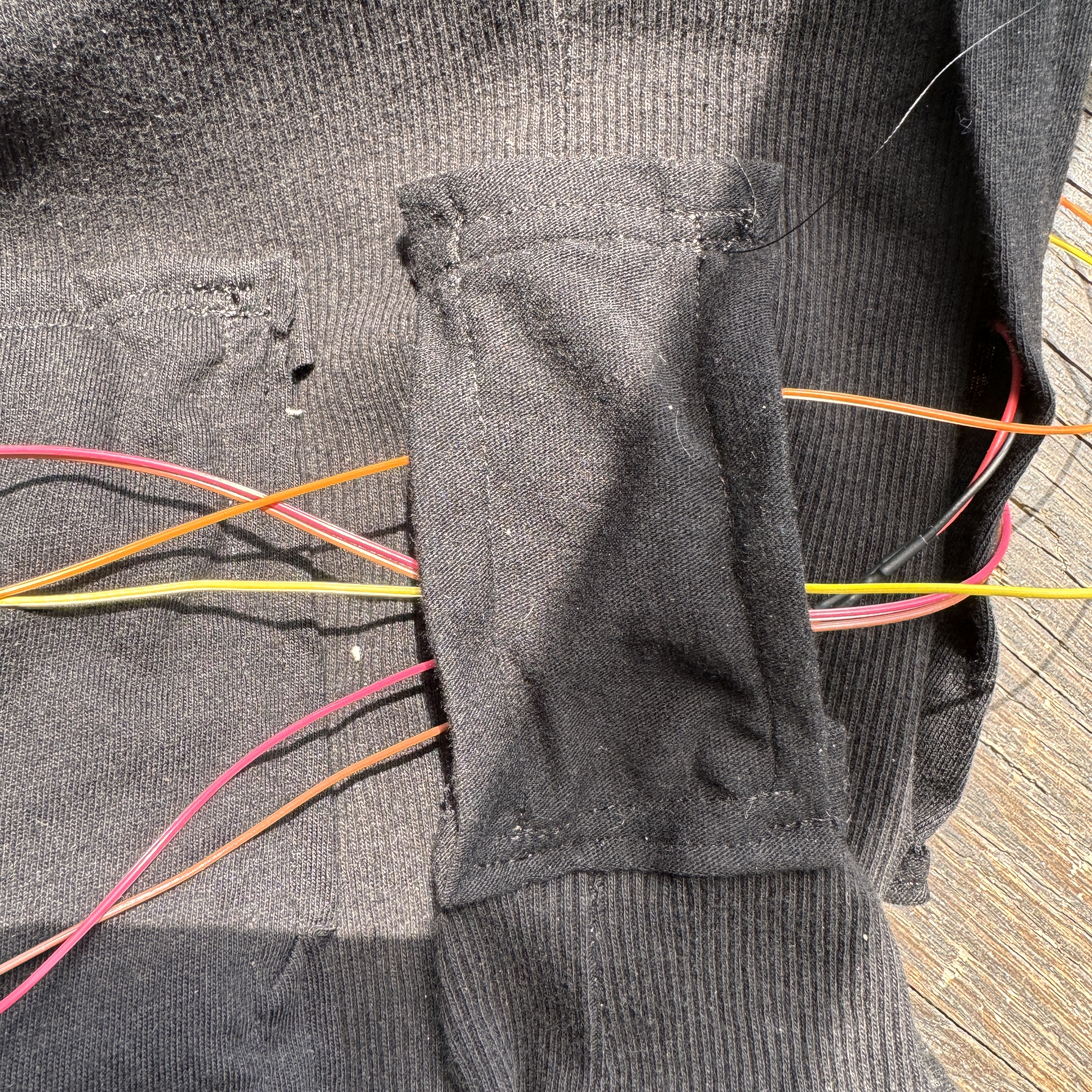
This was relatively straightforward. I soldered three sets of 2 heat pads each. Each pair of each pads was wired in series and the 3 sets were wired in parallel. This allows for some customization if I don't want to use all the heat pads every time. For example, the side pads are attached to each other, so I could take those out and just wear the front and back pads if I wanted to. This also was optimal for my circuitry. This way, they requested 10V (9V supplied - more on that later - but close enough) at 1.5A, which is within the rating of the battery. There was some long wires that I had to run because I didn't want any wires going across the zipper, so instead of routing wires from the front right pad across to the PCB, I had to route them all the way around my body, but I think this made it a much better product. I used ribbon cable for all of this, which is nice because it's stranded and therefore more flexible, but also annoying because it's not as solid as solid core wire is. It was necessary for mobility though. I connected the heat pads to JST connectors that could fit into the sockets on the PCB.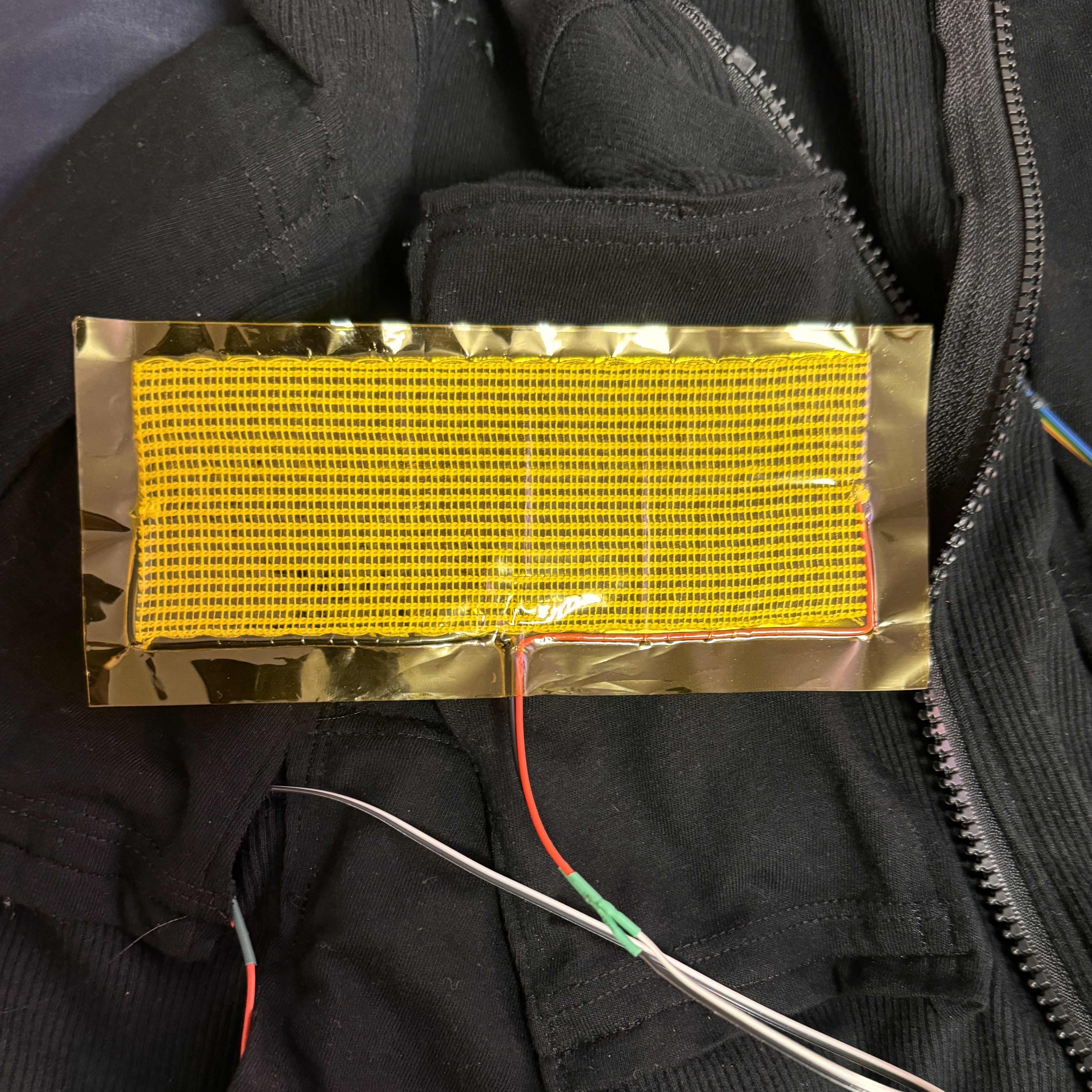
Circuitry
Code
Finally when I felt like I had made so much progress on the hardware, I could start in on the software. Luckily, I had a lot of this logic already written for the MVP, I just had to change it up a bit. First, I integrated all three heat pads into the code and had them turn on and off together. In retrospect, I could have just hooked these up to one Xiao pin, but if I ever want to do zonal heating, this will be nice to have. I also tried to get some LEDs to work, but was having issues - more on that soon. I then wanted to get my encoder working and being able to set a target temperature. Despite following many online tutorials of getting a rotary encoder to work with an ESP 32, I could not for the life of me get mine to read. I troubleshot for hours, trying literally everything to get this stupid encoder to work. I even thought it might have been a PCB issue, which is why I cut the trace and bridged a connection, but even that didn't work. Following the triumphant return of Bobby and some additional troubleshooting with him, he hacked into the mainframe of my computer and pulled up some obscure file that showed that the pin numbers did not even come close to matching up with the actual pins used by the Xiao. Like pin 6 is actually 21 unless you put D6 in front of it. Armed with that knowledge, I put D in front of the numbers in my code and it worked perfectly. I then had to figure out I2C, which was honestly much more straightforward than I thought it would be. I feel like it's rare for me to find a protocol or really any package on the internet that I think is elegantly designed, but I liked I2C. I used that to connect my two temperature sensors and screen to the SCL and SDA pins and control them each individually. I was able to get the temperature readings from the BME printed onto the OLED. From there, I started to incorporate the encoder into setting the target temperature and logic around the code to make it so that the heat pads respected the target temperature. In the end, the code did a couple main things: Allowed me to set a temperature that the pads would heat up to until they reached it, at which point they would turn off and let the temperature cool down until it reached a set threshold (2 degrees in my case) below the target temperature, at which point it would heat back up again; locked the encoder from adjusting the temperature by default to prevent accidental changes, but unlocking it with a click of the encoder and relocking with either another click or 5 seconds of inactivity; lit up the red LED when it was heating and the green LED when it was in range; and displayed the temperature, target, and heating status on the screenPCB Case
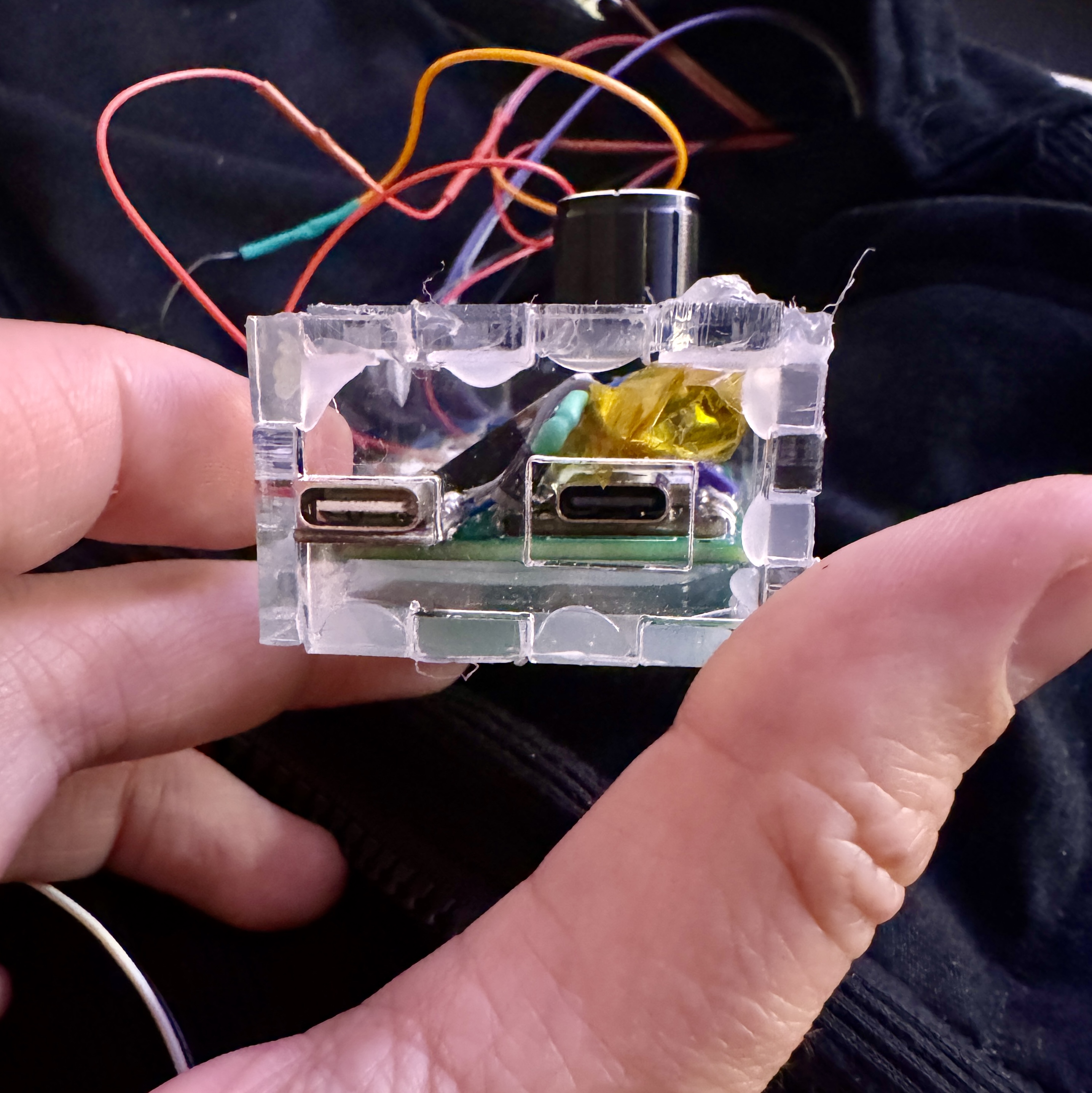
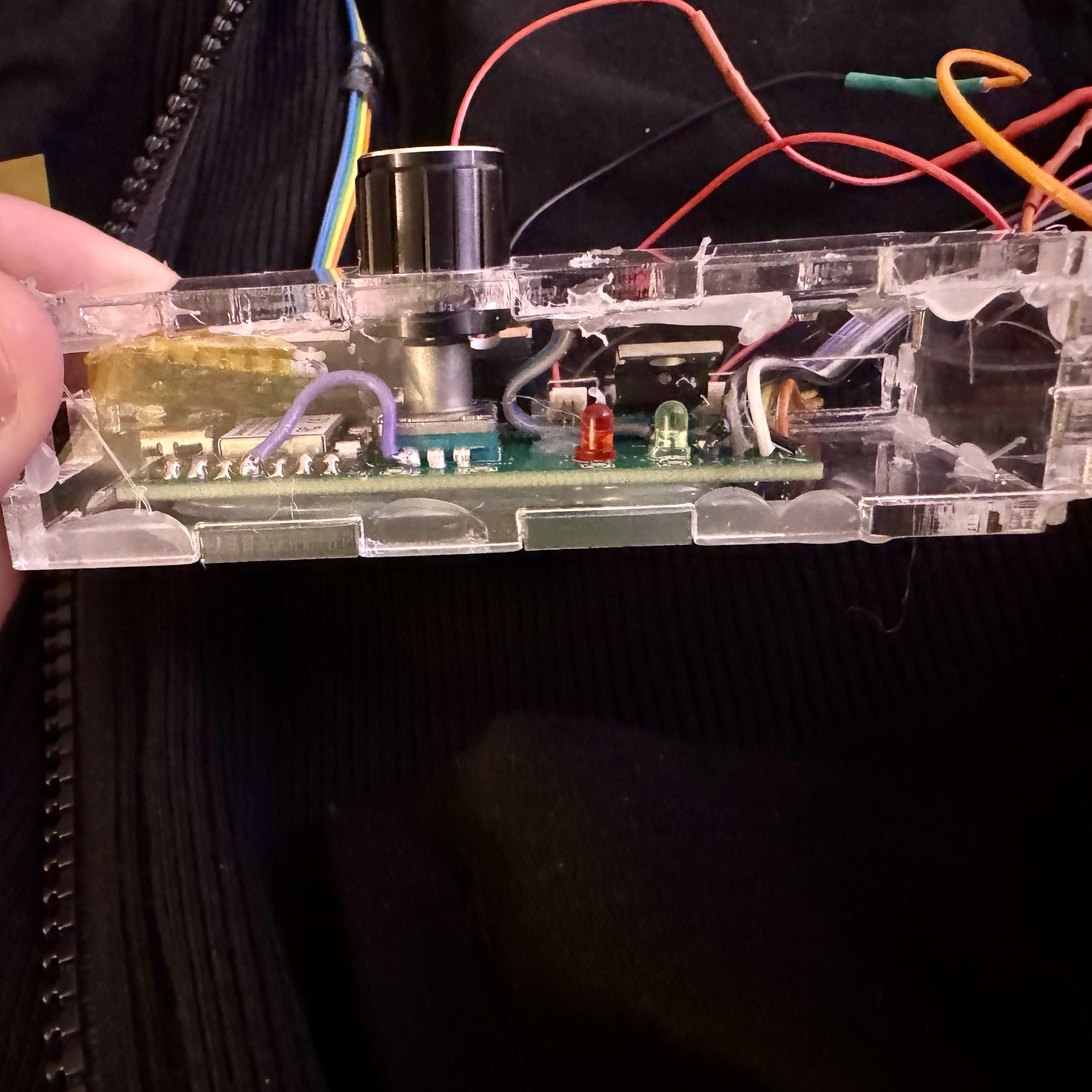
The final step was to make a housing for the PCB. I was originally planning on 3D printing a box for this, but I decided that it would a) take too much time and b) be easier and more straightforward to fabricate the box another way. Our first assignment in this class was to make a finger joint box, so it only felt right to make a finger joint box as the last part of my final project for the class. I took all the necessary measurements, cut a few iterations out of cardboard to test fit, sizing, and port placement, before eventually cutting it out of clear acrylic. I ended up really liking this approach because the clear acrylic showcasing the PCB that I designed is really just the cherry on top of this whole project. The acrylic is so clear it makes the PCB look like a museum piece behind glass, and I just absolutely am in love with it. It also allowed me to place the screen under the acrylic, protecting it from scratches and other stuff that could screw it up. Despite some hiccups along the way with installing the PCB and hot gluing it all shut, it turned out pretty cool, and it serves its purpose of protecting the PCB, while allowing access to the knob for temperature control, all of the pad ports, and both the power and code ports, all while also being able to see the screen and everything inside.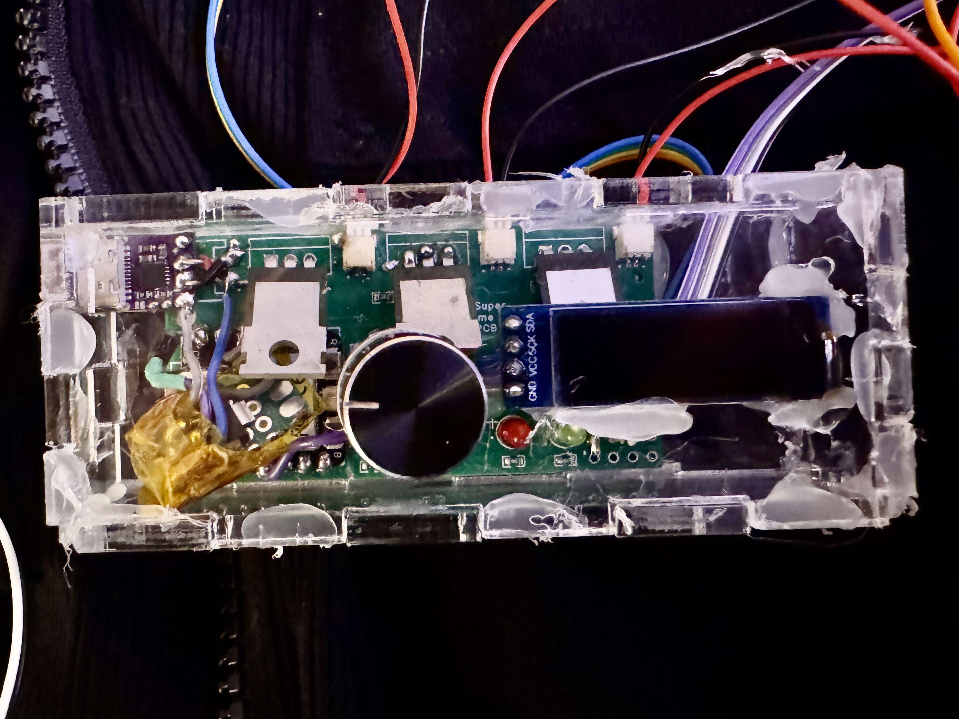
Post Mortem Analysis
I am now writing this post fair, and I wanted to break down both my favorite and least favorite parts of this project, as well as what I will be keeping and what I will be changing when I make V2 of the heated vest, which will be coming at some point before next winter.Pros:
- The vest itself is awesome - I think that I really did a good job with constructing the vest, sewing and frankensteining it all together, and putting the pockets on. Especially for my first time sewing, I am super happy with how this turned out physically
- The washability - making all of the electronics very easily removable is so cool because it will allow me to wash just the vest and keep it nice and clean without damaging the electronics
- The battery usage - having this be USB-C PD compliant is just so cool and allows for so much flexibility. I always carry around a portable battery, and the vest will accept any of the ones that I have and use it to power the vest. Also, if I am ever wearing the vest and need to charge my phone, I have the battery and the cord needed to do that.
- The PCB itself - while there are some tweaks that I will make that are talked more about below, custom designing the PCB was awesome and for 95% of the necessary functionality, it worked great. It was a really elegant solution to my circuitry requirements that, while it did need some adjustments, worked really well overall, was super cool, and was rewarding to design.
Cons:
- Durability - right now, a lot of the connections are really flimsy and shift and change with a slight shake or tap. In V2, I want to make this really wearable, so I need to make it so that those connections can stand the test of time
- Cable management - I feel like right now it's good but not great. Maybe tightening the channels or some other way of funneling those better would significantly improve the project both functionally and aesthetically
- The case - while it is gorgeous, it could be more so and more elegant. It is currently all hotglued together, which makes it a little uglier than it has to be, and it makes it really difficult to open up if/when stuff goes wrong. Even having the laser cut box with 3D printed brackets or something would greatly improve aesthetics and usability.